Sunday, June 7, 2015

The Devil is in the Details

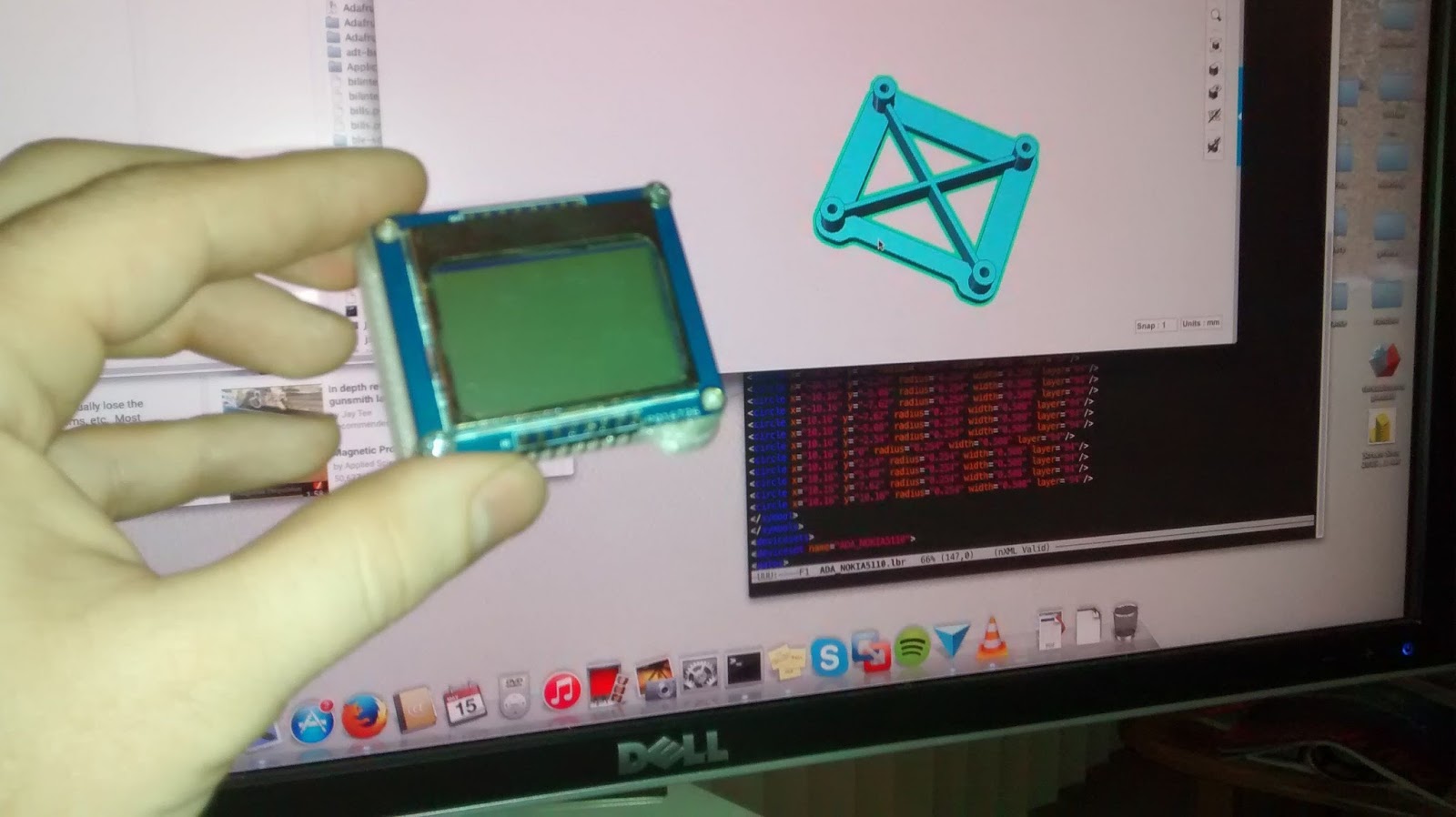
Comparing version 1 and version 2: the new version isn't substantially larger, and looks a whole lot better.
I really thought I was pretty close to finished at this point. Just a few more things to do, but then it occurred to me: how do I get these two case halves together? I had left out screw posts for this on purpose, but now I was wondering if the enclosure was large enough.

My original plan was to mount the screen from the back with screw posts. And this worked just fine. If I were using a more sophisticated CAD package, I could have just gone back and maybe increased the size of the enclosure a bit, whacked in some screw posts, and called it a day. But in 123D, it's hard to revisit early design decisions unless you save lots of versions. Which brings be to my next piece of advice: Save early, save often, and save lots of different versions. In fact, every time I make a major design decision, I save another version. This is because sometimes a design iteration doesn't pan out, and the best course of action is to go back to an earlier version, and work forward again. 123D will allow you correct your mistakes sometimes, but other times it arbitrarily doesn't.


But then there was the question of buttons. What to do with those? And what about the main board? How to mount all of this stuff?


Decided to switch to my black PLA to print out the next iteration. It looks good in black.


I decided to abandon the idea of attaching the screen to the bottom from the back. Instead, I made some clips to hold the screen to the top of the case. This worked better than I was expecting it would. I also made a custom 30mm knob for the encoder.


Unfortunately, my screw post placement definitely caused some issues for mounting the main circuit board to the screen. There just wasn't enough clearance. Also, I need this thing to be at least somewhat weather resistant. It's going to be perma-mounted to the bike, and it will get wet. The button cut-outs just seemed like they'd be hard to seal up.

I decided to try an experiment. Version 1 of the remote needed a little maintenance. After 9 months of being permanently mounted to the bike, the buttons had fallen off, some of the mounting tabs had broken, and rubber I had mounted to seal the button holes was peeling off. Since my CAD skills had improved greatly since I'd done that version, I decided to redesign the enclosure again, and try a little experminet while I was at it.

 I took an entire packet of Sugru and pressed it through the back side of the enclosure to form a membrane. It used a dowel to sculpt the underside of the sugru, to help make it flex the way membrane keyboards do.

This turned out not to work very well.

 I did my best to sculpt the buttons in to button shapes, but in the end the texture of my fingers and the unevenness of the material give you a very DIY look. Not good.

Still, I would have lived with it for a while if it had worked mechanically. But it didn't. Sugru is basically silicone caulk with some talcum powder added to it to give it some ability to hold its shape. The problem with this is that it makes the cured product very brittle. The silcone had the right springiness to it, and actually worked as buttons. But after about 3 or for test presses, the Sugru cracked. Oh well, back to the CAD package.

I had bought a roll of Ninjaflex a while back. I decided to see if I could 3D print a button membrane. I also 3D printed a test fixture and started playing around with different designs. My first test didn't have enough give to it, but my second test worked pretty well. It had enough give to it to provide good feel with gloved fingers, and at the same time it sprang right back to its original position.


I went through a bunch of iterations on this, varying the wall thickness and shape to get a feel for how the material behaved. It's not quite as soft as neoprene, or silicone. What I learned is that the wall thickness needs to be at least 1.0mm to get a successful print. But a 1.5mm wall thickness results in too stiff of a membrane. I also found that I could vary the sensitivity of the membrane / switch system by varying the depth that the membrane has to be flexed to actuate the tact switch underneath. Good. This means I can tune the system. It gives me flexibility to mount the tact switch at almost any reasonable depth under the main cover.

I also figured out that it works best with a slight interference fit: i.e. the outside dimensions of the membrane should be identical to the dimensions of the hole they pass through. This gives a nice snug fit that's not too difficult to insert or remove.

Meanwhile, I was still struggling with how to get the buttons into the enclosure I had designed


Originally, I was going to make a membrane that could be pressed through the enclosure from the back side. The trouble with this is that you basically have to glue it in place, and as Ben Heck says, you need to "build things you can take apart." So I decided to make little covers that can slip into place from the front side. Here's another piece of advice: make test pieces when you're trying out new ideas. This is because the test piece can be only as large as needed.


I create the test pieces by first duplicating the part I'm interested in, and then subtracting away the portion of it that I'm not interested in. Usually I'll delete the test part from the file after I've learned what I wanted to learn.


This experiment proved to work pretty well. Confident I had a way to create a front cover with water-resistant controls, I decided to finally start working on getting all the electronics into the enclosure.

Right away, I hit a snag: my attempts to cut a notch out of the protoboard so it would clear the button openings resulted in a shattered proto-board. I was going to have to design and make a custom board, or wire the controls to the board the old-fashioned way.


Not being an expert in PCB design, I chose the latter approach. I started with a smaller PCB and spent some time just trying different arrangements of boards and components. Amazingly, I managed to squeeze it all in.


Here's a side view showing that by using two right-angle headers, I would have just enough clearance between the screen and the main board.
Testing that the Blend Micro can fit on the under-side of the board.

I knew I was going to need to use some Molex connectors to wire the buttons to the board. But I was dreading having to crimp on a dozen or so of these little itty bitty connectors. I had gone to RadioShack to look for more 3D printer filament, and suddenly I saw the solution: pre-cut, pre-made wires with the female molex pins attached. Perfect!
You just pull the wires out with a small screwdriver, and stick them into your other female molex headers. They don't lock into place in the ones I bought from digikey, so a little dab of hot glue is a good idea to hold them in place.

Testing a couple of button cover designs. One is a dome, the other is kindof more "nipple" shaped, for lack of better word. The latter design is lower profile, but offers a bit more resistance. In the end I decided against it because it was too hard to use with gloves.


I also experimented with a smaller back cover. The electronics actually did fit.

The next sequence shows the circuit board assembly process. I proceed incrementally, and make sure I'm on the right track before moving on to the next phase.


I'm getting better at bodging together circuit boards on perfboard. This only took me about half a day, vs the 2 or 3 days my first project took. Said first project is sitting in the upper-left corner of the image below.

With the board half assembled, I couldn't wait to do a test. I hadn't hooked up the power leads, so I had to run it off USB with the back cover off.

I initially liked the design better in black, but I got a nice surprise when I powered it up for the first time. The LED back-light shines through the natural clear PLA and the result is pretty cool. I kinda wish I had room / time / motivation to throw a few more LEDs in there.

Time to hook up the buttons. This proved to be the most challenging task. As Ben Heck says, wires take up a lot of room in your project. They took up all the remaining room in the case. I wasn't able to use my shorter back cover.
Part of the problem is that I have no choice but to hot-glue things in place, solder the wires, and the cover all the connections with still more hot glue. This makes eats up valuable room when clearances are tight.


But still. I got it done. I mean. Wow. Just look at it. I can even take it apart.

The back cover on. It fits.


Okay, well, if I'm honest, it is pretty funky. Maybe above-average for an initial prototype? But not exactly marketable. Please feel free to comment, critique, whatever. I think it would look better in black, with red buttons, maybe. But I don't have red NinjaFlex.


Also, I do like the glowing translucent effect when the backlight is on, though it might be too dazzling at night. We'll see.

Tragedy

So, having got all that done, I was so excited that I had to try it. And it worked, at first. I had to take it apart to fix a bad ground.

When I re-assembled it, I wasn't paying attention and got power leads reversed, and so dumped 9.6V into the regulator in the wrong direction. And let the magic smoke out of the voltage regulator, and possibly other things.

Whoops. It's a SOT-23 package, so I don't think I'm going to be repairing that micro-controller. I have ordered another one, which should arrive Monday. But I'm going out of town next week, and won't have time to hack on it until the week after next. I am hoping the screen isn't damaged.

But still, for one, brief, shining moment, it was alive. A moment I managed to capture on video. And the rush I get from a moment like that is why I work so hard on these things in the first place.


Progress

 After getting the on-screen UI fleshed out, it was time to start on the bluetooth communication. During the process of all of this, I developed a new-found appreciation for C++ and a new-found hatred of Java. I actually really enjoyed doing the embedded firmware in C++, but writing the android interface was a huge pain the ass.

I will do another write-up on the software portion of this. Right now I want to focus on the product design aspect of it. See, I care about what I build. I want to make sure it works as well for me as I can make it. So I do a lot of iterations.

My 3D Cad skills are constantly improving. I'm new to the whole game, but I have found Autodesk 123D to be the only free tool worth my time. I had looked at Sketch-Up, but the problem is that it's a mesh modeler. This is fine if you don't care about actually making the things you design. But I want to actually build these things, and so a B-REP cad package is a must. This is because B-REP operations (extrusion, revolving, filleting, chamfering, etc) correspond really nicely to the way we actually make physical objects. Also, the models are fundamentally always manifold (i.e. they always have a finite interior volume due to the nature of the math that underlies B-REP modeling). This is important when you go to 3D print your model. With 123D, I found that files almost always export cleanly to .STL for printing. And even when the STL output has errors, I've still had no issues slicing the resulting files, and no print failures resulting from glitches in the CAD software.
The first thing I did was to measure the dislplay with calipers and try to get the hole spacing right. To test this, I made a little stand for the display. If I could screw it on without problems, then I knew the hole spacing was close to correct.

As and aside, the joy of 3D printing is being able to have an idea, and then see it realized in physical form. Forgive my language, but this is fucking cool!. It reminds me of when I was a kid. I'm going to date myself here, but I was 10 when my family got our first color printer, and for the first time I could see what I'd drawn printed out on the page exactly as I'd drawn it.

Who gets excited about printing things out on a page any more? I sure don't. But printing out an object that literally existed only in my imagination a few minutes ago? That's the world we live in now.
So, knowing I had the underling dimensions right, I decided to build an enclosure around it. It was thinking that it maybe needed to be at an angle for some reason. I don't know why. I was really just trying to be artistic. My first attempt, though, wasn't all that successful.
Maybe ... maybe...
Ugh. No. Just no.
I went back to a simpler wedge shape, but by filleting the edges and making a screen cut-out, I caqme up with something that actually seemed worth building. It kinda reminds me of a scaled-up Tamagutchi, or the first cycle computer I had back in the '90s.

Here's my second piece of advice: Use translucency when modeling so you can see interior features.

It's especially important when you are trying to align features like screw posts. Translucency allows you to really see the internal geometry of your part. Issues like thin walls and clearance issues are all but impossible to spot otherwise.
  
I kept the 22.7 degree angle, beacuse I thought it might make mounting on handle-bars easier. I also thought that I might need a lot of room inside, because through-hole electronics are bulky. I've been burned by this before. But also, I just thought it looked kindof cool this way.
I literally couldn't wait to print out this version, and to my surprise, by printing it facing up, I got really good results. I was happy with the overal shape and visual look of it. The cut-out in the shell framed the screen, and the contours of the exterior lead the eye in such a way that it looks smaller than it really is. I definitely avoided the tiny-screen-swallowed-by-large-enclosure look that so many DIY projects suffer from. So what if the styling is a little dated? It looks like something you might have found at Fry's in like 2001, which is a huge leap forward from something you might bought at RadioShack in 1989.

I tell myself that when this is all over, I will order a high-quality 3D print of it from 3D hubs so this design won't be marred by the ugly 3D-printer staircase effect.
However, my elation was short-lived. With my gloves on, it was clear that the button holes, while visually pleasing, were awkwardly placed and much too small. That's what's so weird about 3D modeling. What you see on the screen is often not what you expect when you see it in physical form. Usually things just seem to be a lot smaller than you'd imagined.

This is why it's so useful to have your own printer. Oops. I don't like it. Oh well, let's try something different.
The other issue that came up is that the encoder knob looked a little odd sticking out at an angle. A little strange. And then, to make matters worse, the knob felt way too skinny with my gloved fingers. It felt too fiddly to adjust it.
 I'm a big fan of Sugru. I have a few packets of it that were getting to the end of their shelf life, so I decied to try a little experiment. Could I smooth out the apperance of my 3D printed enclosure by covering it in a layer of silicone putty?

The answer is "kindof." It photographs well, but the in-person effect is very "DIY" looking. Even using the soapy water trick, it's really hard to get a smooth texture. Your fingers dent the material wherever you touch it. So you get one part smooth, but then have to go over the part you were just holding it by. I liked the color though. It definitely added something to the design.
I was pleased that the integrated board stand-offs printed properly. But I intentionally hadn't included bosses to secure the two halves together. This was really more of an experiment.
Still can't help but feel like I'm on the right track here.
This was my first attempt at enlarging the buttons. And honestly, I wish I could have just stuck with this version. Out of all the things I tried, this still looks the best to me.