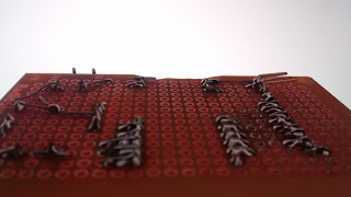
My attempt to salvage the BlendMicro from the old circuit board was not successful. I was going to have to re-do the board. So I re-did it different. I put all the buttons and knobs onto the same board, and then attached the LCD on a riser, as before. Also, this time I added diodes on the power connection to protect from reverse voltage :P.


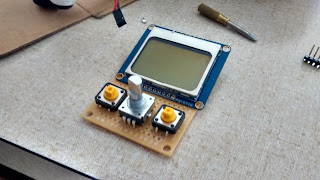


One of the issues I ran into here is that the screen could not be centered, due to the 0.1" spacing. I would have to account for this in my case design.
I did something slightly different than with the previous iteration. I mocked up the electronics in CAD, and then was able to reference the enclosure design to them. I would prefer being able to do things the other way around, but that requires being able to do a custom PCB layout, and I don't have the skill for that yet. Also, 123d design can't export sketches, so there's no way to reference component placement to the 3D model of the housing.
I did something slightly different than with the previous iteration. I mocked up the electronics in CAD, and then was able to reference the enclosure design to them. I would prefer being able to do things the other way around, but that requires being able to do a custom PCB layout, and I don't have the skill for that yet. Also, 123d design can't export sketches, so there's no way to reference component placement to the 3D model of the housing.


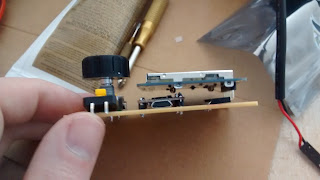
Fortunately, the encoder knob could be centered, so I was able to use this as a reference point for the entire design. It still took a couple of tries on the 3D printer before I had the dimensions correct. But once I did, I was able to reference the openings for the screen and buttons off of that. And that ended up being correct almost on the first try.
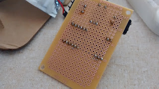
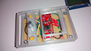
Once I was satisfied with the basic component placement, I wired up all the connections.
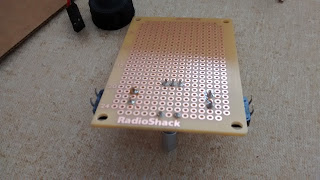


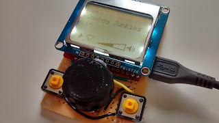
Once I was satisfied that it all worked, I made this test to check that my dimensions were correct.
Once I was satisfied with the basic component placement, I wired up all the connections.


Once I was satisfied that it all worked, I made this test to check that my dimensions were correct.

It took a few iterations to get to the final case design. Once again, screw placement was the bug-bear of the whole project. I was trying to keep the over-all size down, but kept running out of room for screws. And 123d design doesn't make it easy to go back and change fundamental things like the under-lying dimensions, so I had to start almost from scratch 3 times before I got it right.


Here's the first printed version with mounting tabs on the sides.

I ended up not liking that the tabs on the sides. I re-did it with mounting tabs on the top and bottom. For some reason, I thought it made sense to offset the top tab. I changed my mind about that and moved it to the center.


Added a dollop of hot glue between the MCU and the screen for added rigidity and insulation.

Final design coming together.


Finishing touches with Sugru as a gasket material.

And yet I still have issues with the encoder knob and buttons being too close together. During my first road test, I had trouble skipping tracks without accidentally hitting the volume knob. I eventually figured out how to do it, but it takes some practice.
So, if I have to do it again, I need to space the buttons out more, or mount them sideways.

So, if I have to do it again, I need to space the buttons out more, or mount them sideways.

The other issue I ran into is that since Android has only 16 steps on its volume scale, I found that one step per encoder click was far too sensitive. So I had to scale the encoder input. But the whole thing now feels too sluggish, since I had the volume display update only in response to the round trip. This keeps the volume in sync with the display, but makes everything feel unresponsive.
In hind-sight, I guess what I can say about this is that an encoder wheel actually doesn't work very well as the volume controller. If android could adjust volume in finer increments, it would work a lot better. Another thought might be to make the encoder knob harder to turn so that it's harder to accidentally bump it. And also so that it takes more effort to move one step, one is unlikely to move it too quickly. But that might compromise the encoder's value as an input device for scrolling through menus (not yet implemented).
In hind-sight, I guess what I can say about this is that an encoder wheel actually doesn't work very well as the volume controller. If android could adjust volume in finer increments, it would work a lot better. Another thought might be to make the encoder knob harder to turn so that it's harder to accidentally bump it. And also so that it takes more effort to move one step, one is unlikely to move it too quickly. But that might compromise the encoder's value as an input device for scrolling through menus (not yet implemented).
The encoder's button works good, though. And the rubber button pads actually feel pretty good, even with gloves on. So, I'm pretty happy with that.


But there was another problem: vibrations. I figured something like this might be a problem, so I had padded my handle-bar mounts with Sugru.
I designed this mounting scheme
shamelessly cribbed from an action camera I also own. The original
intention was to have inter-operable components, but it turns out that
the precision of my 3D printer and the quality of the materials I use
are both factors, and so the mounting clip failed after a few weeks of
use.


But there was another problem: vibrations. I figured something like this might be a problem, so I had padded my handle-bar mounts with Sugru.

But the bars still transmit some very strong, high-frequency stuff at particular RPMS. In my case, very close to my cruising RPM. And the result was that the display would wig out. First, the contrast would get very dark, then the display would cut out all-together. Strange! But was it mechanical or electrical interference? I tested this by taking the display out of its clamp and holding it in my left hand while riding along at 5000RPM (I do NOT recommend doing this!) The problem did not re-appear. So my temporary solution was to work the mount a little bit so it wouldn't be clamped so tightly, which solved the problem with the display cutting out. But now the thing tends to fall out of the mount.
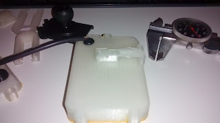
My original thought might be to cast something out of sillicone, but my experiments with molding silicone via 3D printed molds have been problematic. Basically, you can't separate the mold from the silicone. So that gives me an idea: don't even try to separate the silicone. Instead, embed the mount in the silicone.


The idea here is to isolate the remote and from the bars by a Silicone cushion. The cavity between the outer shell and the mounting plate will be filled with RTV, and then the plate carefully pressed in and the whole thing allowed to cure for a few days. I added some texture to the inside surfaces to help with adhesion, although my experience is that RTV will stick like nothing else.
I'll do another post on the my experience with mold making.
I'll do another post on the my experience with mold making.